

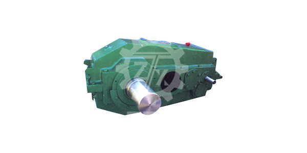
< an overview >
The QY series hard surface reducer for cranes is developed on the basis of QJ series hard toothed reducer. The steel plate is welded and the box is annealed to stress treatment. The gear adopts high quality low carbon alloy steel, and the tooth surface is carburized and quenched, and is processed by a group of grinding in a constant temperature workshop, and the product quality is stable and the performance is reliable.
< two > applicable conditions
1 gear circumferential speed is not greater than 20m/m;
2 high-speed shaft speed, not big 1500r/min:
3 working environment temperature is -40, -+45'C;
4 can be positive and negative two direction operation.
< three > type and speed ratio
< four > mark
One
1 installation type
2 low speed shaft end type
3 assembly type
4 nominal drive ratio
5 nominal center distance (low speed center distance)
S: three pivot support type
6 structure type
Hard toothed surface reducer for QY: crane
Mark down:
Nominal center distance a1=315, nominal transmission ratio i=56, assembly type 111st, low speed shaft for gear shaft, vertical installation three stage transmission, crane with hard surface reducer, marked as reducer QY3S315-56IIICL
Two
Tag example:
Nominal center distance a, =315, nominal transmission ratio i=56, assembly type 111st, low speed shaft for gear shaft end of the three stage transmission, crane with hardened surface reducer, QY3D315-56U, III, C.
< five > assembly type, installation type and shaft end type
1 there are nine types of assembly, as shown in figure 1:
2QY3S, QY4S and QY34S mounting types: horizontal W or vertical L (V). In the deflection angle +a0 range, for horizontal installation; L range for vertical installation. See Figure 2
Note: the degree of a angle is related to the transmission ratio. When the reducer is tilted a angle, it should ensure that the middle gear is 1-2
3QY3S, QY4S and QY34S are three pivot support types, as shown in figure 3.
4. shaft end type: high speed shaft end adopts cylindrical shaft flat key connection, output shaft end has three kinds of patterns (see Figure 4 and table 2, 3)
A.P type: cylindrical shaft extension, flat key, single key connection;
B.H: spline shaft extension, involute spline connection;
Type c.C: gear shaft extension (only the nominal center distance of 180mm-560mm gear reducer has this type of shaft end)
< nine > the selection method of reducer
1 determine the nominal gear ratio of the reducer I.
Calculated transmission ratio
Is=n1/n2
Type 1: is, the required drive ratio;
N1, an input shaft speed, r/min:
N2, output shaft speed, r/min:
According to the required drive ratio, i. Select the nominal gear ratio of the reducer i..
2. determine the nominal input power of the reducer PN
PN>P2Xfixf2
Type 1: rated power of P. working machine kW;
The coefficient of F1 working machine is selected by table A according to the load condition of the working mechanism and the grade of use (refer to GB/T38T3811, appendix N)
F2 prime mover coefficient, motor and hydraulic motor fo=l.
Check the maximum torque of the reducer
PN = MnXnlXf3/9550
Type: Mn motor rated torque Nm:
F. The peak torque coefficient is selected by table A according to the utilization level of the load condition of the working mechanism.
4. select the speed reducer according to I. and PN from the power meter (table 10 or 11).
Example: a weight is 32t, span 22.5m continuous bridge crane for loading and unloading, the main lifting mechanism for the static power is 50kW, the lifting speed is 8m/min, speed 18.5rmin, agency level M7: lifting motor rated power 60kW, speed 750r/min. Choose reducer (third assembly form, gear shaft end).
1) calculate the transmission ratio:
Is=n1/n2=750/18.5=40.5
Choose in=40, three stage drive
2) determine the rated input power of the reducer:
PN = P2XfiXf2
By GB/T3811 appendix N, the working level is M7 continuous loading and unloading grab bridge crane, its main lifting mechanism with grade T6, load condition is L3, check table A, get f, =1.2
PN=50x1.2x1=60 (klN)
When the n=750r/min, iN=40, look-up table 10, ai355mm, the reducer high speed shaft allowable power PN=74.9kW meet the requirements
3) check the maximum torque of the reducer:
M, =9550XP1 / n1=9550X60/750=764 (Nm)
Check table A by L3-T6-M7, lifting mechanism f3=10