

< 1 >QJ-LJ lifting l vertical reducer
QJ - L reducer is derived from the QJ reducer, mainly used in the crane car operating mechanism and part of the gantry cranes, loading and unloading bridges and other carts
The running mechanism can also be used for other equipment which needs to be installed vertically and is used instead of the ZSC reducer.
1 features
1) QJ-L reducer adopts cast iron box, and the base type is equipped with vertical reducer;
2) three stage drive with a speed ratio of 16-100:
3) there are 7 specifications in this series. The nominal center distance is 140-400mm:
4) small reducer for oil bath lubrication, more than 280 of the reducer using centralized injection lubrication, other characteristics with the QJ reducer.
2 type
1) structure type Qj-L reducer is three stage vertical belt reducer.
2) assembly type, Qj-L reducer, there are six types of assembly, as shown in figure 11.
3. model
3: assembly type
2: nominal transmission ratio
1: nominal center distance
-L: vertical belt base
QJ: crane reducer
Tag example
The vertical center speed of the crane is 200mm, the nominal transmission ratio is 40, and the assembly type is third type,
Speed reducer QJ-L200-40...
4 main technical parameters
1) the center distance of the center distance type Qj-L reducer is shown in table 17.
2) the transmission ratio of the QJ-L reducer is shown in table 18. The limit deviation of the nominal transmission ratio to the actual transmission ratio is + 5%.
5 outline and mounting dimensions
The shape and installation dimensions of type QJ-L reducer are shown in Table 12 and see table 19.
6 carrying capacity
For QJ-L type reducer, when the working grade is M5, the output torque and the permissible power of the high speed shaft are shown in table 20.
The output torque of the QJ-L reducer and the permissible power of the high speed shaft for continuous operation are shown in table 21.
The instantaneous allowable torque at the end of the output shaft of the reducer is 27 times the rated torque.
< two >QJ-T type set speed reducer for crane
QJ-T reducer is derived on the basis of aj-L reducer, mainly used in the operation of cranes, also can be used in other machinery needs vertical set of transmission, to replace ZSC (A) reducer.
1 features
1) the output of the QJ-T reducer is a conical sleeve, the reducer is sheathed on the passive axis of the main engine, and the end is fixed, and the weight of the reducer is also supported on the shaft. The upper part of the box body is provided with an installation hole which is fixed on the bracket through a pin shaft.
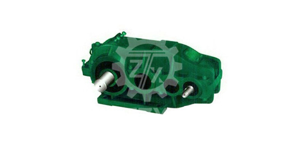
2) the box is divided into three parts, forming a "upper" shape, used as a vertical reducer. The oil in the lower tank is not easy to leak, and the output shaft center line to the lower end of the limit position is relatively small. Other features are the same as Qj-L reducer.
2 type
1) assembly type QJ-T type reducer has four assembly types, as shown in figure 13.
2) shaft end type, high speed shaft adopts cylindrical shaft extension, flat key connection, low speed shaft adopts hollow shaft sleeve, taper shaft hole, flat key connection.
3 model
Tag example
Set type reducer for crane, nominal center distance ai=200., nominal drive ratio i=40, assembly type III
Mark as reducer QJ-T200-40...
4 main technical parameters
The center distance and transmission ratio of QJ - T reducer are the same as those of QJ-L reducer.
3: assembly type
2: nominal transmission ratio
1: nominal center distance
-T: suite type
QJ: crane reducer
5 exterior and mounting dimensions
The shape and installation dimensions of type QJ-T reducer are shown in table 14 and table 22.
6 carrying capacity
The output torque of the QJ-T type reducer and the allowable power of the high speed shaft are the same as those of the CJ-L reducer, as shown in table 20 and table 21.
< three selection methods.
1. selection principle
1) in choosing the reducer, first of all to meet the working conditions. That is, high speed spindle speed, maximum gear circumferential speed, ambient temperature and steering etc..
2) to meet the needs of the mechanical strength, such as the power input shaft (or shaft to insert, shaft extension of the maximum radial force and instantaneous maximum torque. The continuous use of the reducer, but also to meet the heat power.
3) to meet the speed requirements, according to the speed and working mechanism of the original motivation for the requirements of the transmission speed selection closest ratio (the best is the actual reduction gear ratio, if not given the actual transmission ratio with nominal transmission ratio, instead) general both limit deviation of grade 2 + 4%, 3 + 5%. If you have special requirements, contact the manufacturer for special preparation.
4) according to the requirements of the main engine, the installation position of the reducer, the limit size, the connection position and the transmission performance, determine the structure type, installation type and assembly type of the reducer.
5) select the shaft end type according to the connection mode of input and output.
6) consider the convenience of use and maintenance, select the oiling port, the location of the oil drain, lubrication, heat dissipation, etc..
2. select calculation
1) type QJ (including QJ-D, QJ-L and QJ-T), for the crane institutions, according to the design specification of GB3811 "crane" (hereinafter referred to as the "standard") regulations, crane work level is divided into M1-M8 eight, the bearing capacity of listed in this manual work for M5 level. To be used at other levels of work, the formula should be converted.
PM5=pM1X112~kW
Formula pM5- allowable value of power (kW) of the high speed shaft in the bearing capacity table of the reducer:
PM - - the power value relative to the Mi operating level (kW):
I work level 1-8:
2) the basic load of fatigue calculation of crane mechanism Mmax
A) lifting and unbalanced luffing mechanisms
Mmax= phi 6MnNm phi 6=1/2 (1+ Phi 2)
Coefficient of movable load of 6:
Mn- motor rated torque (Nm);